This guide provides a detailed overview of the disassembly process for the flywheel and flywheel housing of the Cummins M11 series engine. The procedure is designed to ensure safe and effective disassembly, helping to avoid damage to key engine components.

Tools and Equipment:
- Cummings INLINE 6 Diagnostic Adapter for Heavy Duty Truck
- Cummings Insite 8.7/8.9.2 Pro Diagnostic Software (Support Calibration Online)
Flywheel Disassembly Steps:
- Bolt Installation and Guide Pins:
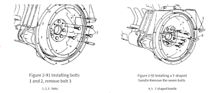
- Install two M10-1.50×40 bolts at positions 1 and 2 as shown in diagram Figure 2-91.
- Replace the bolts with two guide pins, particularly important for REPTO (Rear Engine Power Take Off) configurations to support the crankshaft gear before removing the crankshaft rear oil seal.
- Clutch Pressure Plate Bolts:
- Check the clutch pressure plate bolt holes, which may be 3/8-16, 7/16-14, or 1/2-13. Correctly size the T-handle to fit these bolts without damaging the flywheel.
- Attach two T-handles to the flywheel and unscrew the 7 bolts holding it in place, as illustrated in Figure 2-92.
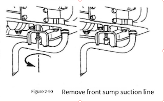
- Remove the oil suction pipe from the front oil collecting tank as shown in Figure 2-90.
- Flywheel Removal:
- Use nylon straps and a crane to safely lift the flywheel, as depicted in Figure 2-93.
- Before lifting, alternately tighten bolts 1 and 2 to help loosen the flywheel from its seating.
- Final Removal:
- Remove the two bolts and the guide pin as per Figure 2-94.
- Take out 12 bolts, the retaining ring, and the crankshaft rear oil seal as shown in Figure 2-95.
Flywheel Housing Disassembly Steps:
- Removing Supports:
- Detach the bolts and two engine rear brackets as indicated in Figure 2-96.
- Housing Removal:
- Unfasten and remove 12 bolts along with the flywheel housing itself as shown in Figure 2-97.
Additional Information:
- Ensure all procedures are followed in the sequence provided to maintain the integrity of the engine components.
- Use the diagnostic software and adapter for troubleshooting and ensuring all electronic settings are correct before disassembly.
This guide ensures that technicians can safely and efficiently dismantle the flywheel and flywheel housing of the Cummins M11 series engine.