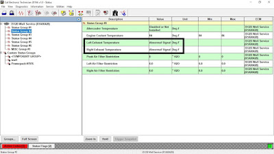
Left or Right Exhaust Temperature – Abnormal Frequency, Pulse Width, or Period.
Read More:
Create Product Status Report (Download List) on Caterpillar ET Software
Pulse Width Modulated (PWM) Sensor
The PWM sensors provide a signal to the engine’s ECM for certain engine operating conditions. The sensors receive a 8.0 ± 0.4 VDC regulated voltage from the ECM.
The sensor’s wires are routed from the ECM to the sensor connectors. The following list gives the terminal locations for the sensor connector.
-Terminal A = 8 V supply
-Terminal B = sensor return
-Terminal C = sensor signal
The ECM provides short circuit protection for the internal power supply. A short circuit to the battery will not damage the internal power supply.
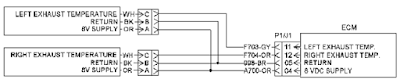
(Pin A) Sensor supply
(Pin B) Sensor return
(Pin C) Signal
Check for an “Active” Diagnostic Code
A. Connect Caterpillar Electronic Technician (ET) to the service tool connector.
Read More: How to Connect Caterpillar ET Software to the ECM
B. Monitor the diagnostic codes on Caterpillar ET. Check and record any diagnostic codes.
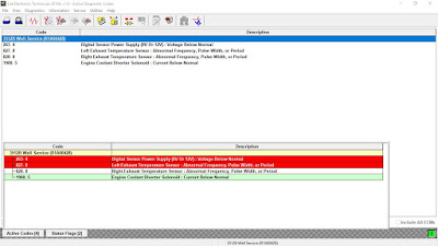
Active Diagnostic Codes – 3512C
-Code and Description:
827-8 Left Exhaust Temperature Sensor abnormal frequency, pulse width, or period.
828-8 Right Exhaust Temperature Sensor abnormal frequency, pulse width, or period
-Conditions which Generate this Code:
The Electronic Control Module (ECM) detects a sensor frequency that is greater than 1000 Hz or less than 150 Hz. The ECM detects a duty cycle that is greater than 90 % or a duty cycle that is less than 10 %.
-System Response:
The value of the parameter is set to zero. The code is logged.
Check the Digital Supply Voltage at the Sensor Connector
C. Disconnect the suspect sensor(s) at the sensor connector.
D. Turn the main disconnect switch to the ON position.
E. Measure the voltage on the ECM side of the sensor connector between pin A and pin B (also pin B and pin C) for the suspect sensor(s).
Expected Result: The supply voltage is 8.0 ± 0.4 VDC.
If OK – The supply voltage at the ECM is correct. There’s a problem with sensor(s) connector, wiring harness or the sensor(s).
Check the Sensor’s Duty Cycle at the Sensor Connector
F. Measure the duty cycle between the sensor’s signal wire (pin C) and pin B of the sensor connector.
-Set the multimeter to “VDC”, and press the “Hz” button twice so that the % symbol is displayed.
Expected Result: The duty cycle is between 10 to 90 percent.
If Not OK – Replace the sensor(s), with CAT P/N: 163-7882.
Read More:
How to Setting or Testing the Engine Overspeed using Caterpillar ET?